On part 2 of building the power supply, we will figure out how to get power in.
I had previously purchased basic computer power cable socket with place for fuse and switch. I was ment to put this on my old power supply but i never got to do that, so i decided new one will get it.

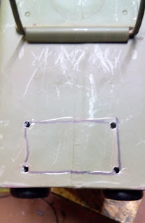
Attaching this to the back of the box is not much different from the display.
Plan.
Drill holes to the corners to cut with dremel.
Then fit. File. Fit. File more and make it fit.
Next in turn was preparin the heatsink. I chose maybe bit massive 60x80x40mm heatsink that once belonged on AMD processor i found from scrap box . To this i drilled holes for the regulator and power transistor. I tapped the holes with M3 threads so i don't need to put a nut on the other side.
PCB connected on the heatsink. Seems to be nice and flat with bottom of the PCB.
Other angle. PCB is bit pointing upwards because power transistor was not completely straight. Little bending fixed this.
For the whole thing i made a cradle from 0.7mm sheet metal. I drilled holes matching the holes on the PCB and also one bigger for the slot on the heatsink.
PCB attached to the cradle. Seems to be fitting all right. It's standing on M3 machine screws and on bottom of the PCB there is double nuts to make air gap between the PCB and the cradle.
Sideways picture of the whole assebly. Heatsink will be held in place with piece of M5 threaded rod.
On the edges of the craddle i drilled holes to mount it on the sides of the ammo box.
And PCB in place.
On the next part, we'll plan how we make the front panel look like.
-Jokke


No comments:
Post a Comment